EN
- CH
- EN

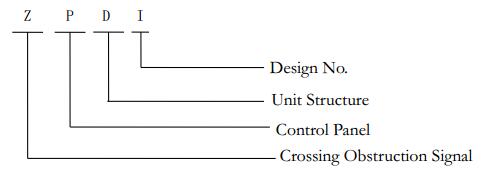
ZPD-I
ZPD-I Unit Control PanelZPD-I Unit Control Panel
ManualApplication
Unit Control Panel of Highway Level Crossing Obstruction Signal (hereinafter referred to as “Control Panel”) is mainly used for different kinds of highway level crossing obstruction signal equipment, which enables the gatemen to monitor and control the highway level crossing obstruction signal equipment. The customized unit Control Panels of highway level crossing signal are also available.
Product Models
Models and Symbols
Structure
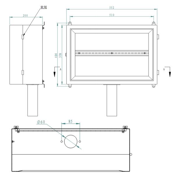
Installation
It is advisable to choose an easy to operate and observe site of the highway level room and install the Control Panel on the wall by 4 ¢8x50mm expansion bolts , where is 1500mm above the ground. See the dimension indicated in the Legend 1.
Notes: Follow the electric interlocking construction specifications, pass the post-protection cable through the ¢60 protective tube under the Control Panel; Fasten the skin of the cable on the bolts next to the protective tube orifice; Pour into insulation paste after cable is distributed as same as the Legend.
Follow the electric interlocking construction specifications, clean and fasten the both the inside and outside the Control Panel while a power test is a must; lock the Control Panel after all the buttons and indictor lights are tested.
Instructions on Control Panel Buttons and Indicator Lights
See the Interface of the Control Panel indicated in Legend 2
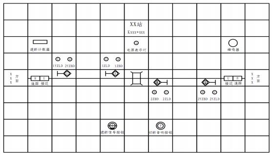
Legend 2 Interface of the Control Panel
See the Legend 1 for Letter Symbols of the Control Panel
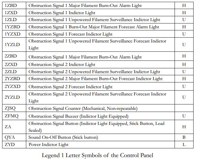
Legend 1 Letter Symbols of the Control Panel
1) XXX
Crossing Name
2) KXX+XXX
Crossing Coordinates
3) Obstruction Signal Counter
Count 1 when the button is pressed for1 time.
4) Power Indictor Light
Power indictor light for all the indictor lights on the interface, red color, which indicts the power supply is normal when it is on; abnormal or power-off when it is off.
5) 1YZLD:
Obstruction Signal 1 Unpowered Filament Surveillance Forecast Indictor Light , yellow color.
When the obstruction forecast signal 1 is off: the light will be on indicating the major and unpowered filaments as well as the lighting circuit are complete, unpowered filament surveillance circuit works normal; the light will be off indicating either the major or unpowered filament burn-out or filament surveillance circuit failure.
The light will be off when the obstruction forecast signal 1 is on.
6) 1YZBD:
Powered Filament Alarm Light of Obstruction Forecast Signal, red color.
The light will be off when the obstruction forecast signal 1 is off, or the obstruction forecast signal 1 is on, but its main filament and lighting circuit are complete.
The light will be on when the obstruction forecast signal 1 is on and its main filament burn-out or light circuit is incomplete.
7) 1YZ:
Obstruction Forecast Signal 1 Repeater, yellow color.
The light will be on when the obstruction forecast signal 1 is on
8) 1ZLD
Obstruction Signal 1 Unpowered Filament Surveillance Indictor Light ,yellow color.
When the obstruction forecast signal 1 is off: the light will be on indicating the major and unpowered filaments as well as lighting circuit are complete, unpowered filament surveillance circuit works normal; the light will be off indicating either the major or unpowered filament burn-out or the lighting circuit is incomplete or filament surveillance circuit failure.
The light will be off when the obstruction forecast signal 1 is on.
9) 1ZBD:
Powered Filament Alarm Light of Obstruction Signal, red color.
The light will be off when the obstruction signal 1 is off, or the obstruction signal 1 is on, but its main filament and lighting circuit are complete.
The light will be on when the obstruction signal 1 is on and its main filament burn-out or light circuit is incomplete.
10) 1Z:
Obstruction Signal 1 Repeater, yellow color.
The light will be on when the obstruction signal 1 is on
11) 2YZLD:
Obstruction Signal 2 Unpowered Filament Surveillance Indictor Light, yellow color.
When the obstruction forecast signal 2 is off: the light will be on indicating the major and unpowered filaments as well as lighting circuit are complete, unpowered filament surveillance circuit works normal; the light will be off indicating either the major or unpowered filament burn-out or the lighting circuit in in complete or unpowered filament surveillance circuit failure.
The light will be off when the obstruction forecast signal 2 is on.
12) 2YZBD:
Powered Filament Alarm Light of Obstruction Forecast Signal 2, red color.
The light will be off when the obstruction forecast signal 2 is off, or the obstruction forecast signal 2 is on, but its main filament and lighting circuit are complete.
The light will be on when the obstruction forecast signal 2 is on and its main filament burn-out or lighting circuit is incomplete.
13) 2YZ:
Obstruction Forecast Signal 1 Repeater, yellow color.
The light will be on when the obstruction forecast signal 2 is on
14) 2ZLD:
Obstruction Forecast Signal 2 Unpowered Filament Surveillance Indictor Light, yellow color.
When the obstruction forecast signal 2 is off: the light will be on indicating the major and unpowered filaments as well as lighting circuit are complete, unpowered filament surveillance circuit works normal; the light will be off indicating either the major or unpowered filament burn-out or the lighting circuit in in complete or unpowered filament surveillance circuit failure.
The light will be off when the obstruction forecast signal 2 is on.
15) 2ZBD:
Powered Filament Alarm Light of Obstruction Signal 2, red color.
The light will be off when the obstruction signal 2 is off, or the obstruction signal 2 is on, but its main filament and lighting circuit are complete.
The light will be on when the obstruction signal 2 is on and its main filament burn-out or lighting circuit is incomplete.
16) 2Z:
Obstruction Signal 1 Repeater, yellow color.
The light will be on when the obstruction signal 2 is on
17) Obstruction Signal Button
Red color with leading sealing, 2 position stick button. Press down to turn on the obstruction signal and manually bounce to turn off.
18) Button for Cut-Off Audible Signal
White color, 2 position stick button.
The buzzer works when any of the obstruction signals of the crossing encounters problems of unpowered main filament burn-out or lighting circuit is incomplete or unpowered filament surveillance circuit failure. Press the button of cut-off the buzzer.
The buzzers works again when the main unpowered filament restores or the lighting circuit failure recovers or the unpowered filament surveillance circuit gets repaired. Manually bounce the button to turn off the buzzer.
Service Lives of Main Components
1) The service lives of all the indictor lights that embed in the interface shall be no less than:6X10⁴ Hours
2) The service lives of all the buttons that embed in the interface shall be no less than:100,000 Times
Usage Environment
The Crossing Unite Control Panel shall work effectively under the following circumstances:
1) Barometric Pressure: No less than 70.1kPa (equal to lower than altitude of 3,000 m)
2) Surrounding Air Temperature: -5℃~+40℃
3) Relative Air Humidity:No more than 90%(25℃)
4) No harmful gas nearby that may cause explosion
5) The Control Panel shall be installed in-door of the crossing.
6) The installation site shall be easy to fasten and operate. The Control Panel shall be kept away from rain, long-time exposing to sun, smoke & dust, moisture, and harmful gas, etc.
Transportation and Storage
1) Do not crush and keep away from moisture, chemical corrosion and harmful gas.
2) The Control Panel shall be stored in a chemical corrosion and harmful gas free and clean environment with temperature between -10℃~+40℃ and humidity of less than 80%. The packages shall be opened after 3 months to ventilate.
Maintenance and Repair
1) Keep the inside and outside of the Control Panel clean and dry.
2) Regular checks are recommended although luminous diodes usually have longer service lives.
3) The buttons shall be fully functional during operation and the contacts shall meet the requirements of electrical specification
4) The cable entry shall be well sealed.
5) The Control Panel shall be included into scheduled maintenance together with other signal devices.