EN
- CH
- EN

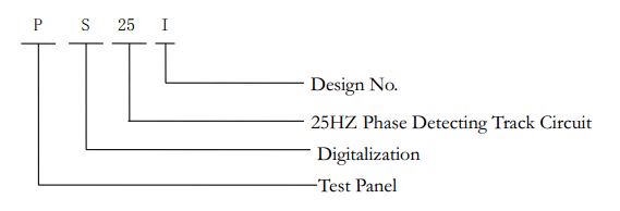
PS25-I
PS25-I Digital and IntelligentPS25-I Digital and Intelligent Real Time Trace Circuit Test Panel
ManualApplication
Track circuit is a crucial signal equipment to determine the location of a train, which often appears troubles because of its complex working environments. Through data collection from the track circuit, digitalized and intelligent real time trace circuit test panel achieves tracking, recording and alarming of track circuit’s working status and accordingly providing supporting data for fault processing.
Adopting modularized and digitalized component structure, PS25-I Digitalized and Intelligent Real Time Trace Circuit Test Panel (hereinafter referred to as “Test Panel”) is specially designed for 25HZ phase detecting track circuit, which is able to synchronously collect and display receiver’s information of 48/26 track circuit section in real time and can be networked through CAN.
Product Model and Technical Requirements
Product Models
Models and Symbols
Structure
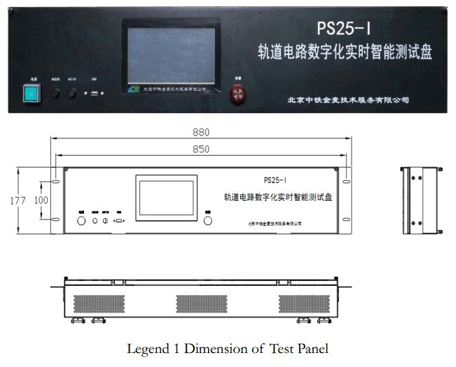
Installation
The Test Panel shall be installed in a free space of a combination sideboard or shelving combination in the signal engineering room. Fasteners are regular cabinet screws.
Instructions on Buttons and Displays
Main Interface
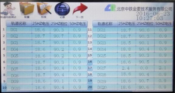
Legend 2 Interface of Test Panel
 To configure names of track circuits and match information collection.
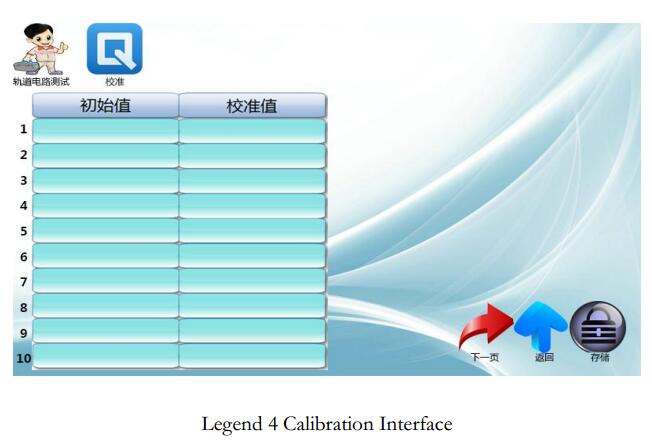
 To calibrate the information collected.
 To record the information collected from all the tracks in real time when the button is clicked. The information will be kept under U flash disk catalogue: \track test disk\20YYMMDD_JL.LOG (open by Windows’ wordpad)
 Click this button to switch to next page. Each page displays 20 pieces of information collected.
 To configure the equipment’ time and enter into configuration interface after click. See the picture below.
Configuration Interface
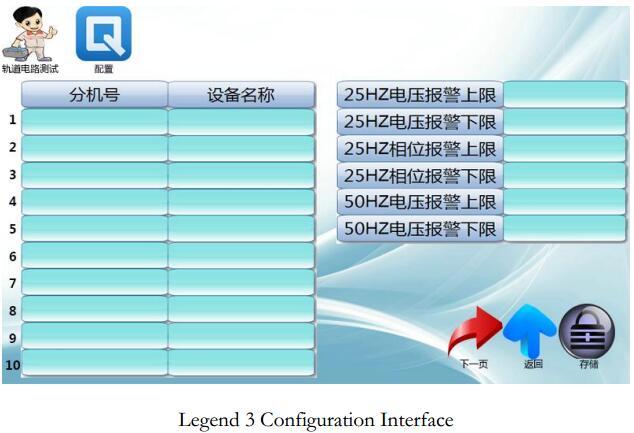
Notes: The alarm information will be kept under U flash disk catalogue: \track test disk\20YYMMDD_BJ.LOG (open by Windows’ wordpad)
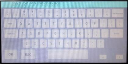
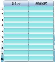 To configure the names of the tracks in accordance with the orders of information collection and wiring.
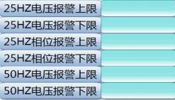 Alarm Upper Bound and Lower Bound
 To store set value.
Calibration Interface
Functions
1) To digitally and intelligently collect 25HZ alternating voltage, phase angle and 50HZ from receiver of 25HZ track circuit. (manual operation free, 48/26 data is updated on second basis.
2) 25HZ signal monitoring range: Voltage电压0~40V; Phase angle 0~360 degrees;
3) 25HZ signal monitoring range: Voltage电压0~40V
4) Monitoring Accuracy: Voltage ±1%; Phase angle ±1%;
5) Alarm: To alarm and record anomalous changes in order to provide supporting evidences for determining track circuit problems through configuring 25HZ receiving voltage of track section and phase angle’s upper and lower bounds of alarm thresholds; to alarm and record the values beyond the limit in order to provide solid evidences for track circuit problems analysis through configuring 50HZ interference voltage of track section’s upper and lower bounds of alarm thresholds.
6) Record: The device will put all the targeted track sections’ information on storage device in real time when the button is clicked.
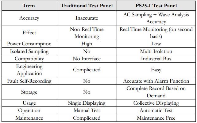
Competitiveness
Usage Environment
1) Barometric Pressure: No less than 74.8 kPa (equal to lower than altitude of 3,000 m)
2) Surrounding Air Temperature: -10℃~+40℃
3) Relative Air Humidity:No more than 90%(25℃)
4) No harmful gas nearby that may cause explosion
Transportation and Storage
1) Do not crush and keep away from moisture, chemical corrosion and harmful gas.
2) The Control Panel shall be stored in a chemical corrosion and harmful gas free and clean environment with temperature between -10℃~+40℃ and humidity of less than 80%. The packages shall be opened after 3 months to ventilate.
Maintenance and Repair
1) Keep the Test Panel dry and table clean.
2) The cable entry shall be firm enough.
3) The Control Panel shall be included into scheduled maintenance together with other signal devices.